Polyisocyanurate insulation (polyiso) has the highest market share in the roofing industry–approximately 75%. It's been the market leader for decades. Why? Because polyiso has the highest R-value per inch of insulating materials that are commonly used in the roofing market. There are other insulation types that come close, but none that are widely used match the R-5.6 to R-5.7 per inch insulating value of polyiso (other than vacuum-insulated-panels and a recently released XPS product). Polyiso is also widely used because of its other benefits: its availability, material compatibility, impact and fire performance, general durability, relative moisture resistance, and its ability to be attached/secured by various methods. Given its characteristics, there's good reason polyiso insulation is a market leader.
Even with all of polyiso's benefits, there has been a lot of discussion in the roofing industry over the last couple of decades about the effect of temperature on polyiso's R-value. The consulting firm, Building Science Corporation, and the National Roofing Contractors Association have been vocal about this topic, and, honestly, their research and commentary have had a positive impact on polyiso's R-value at low temperatures. The industry has responded by providing products that have a more stable temperature-based R-value. New blowing agents and/or formulations of polyiso, including non-halogenated polyiso products, have resulted in more stable R-values at varying temperatures.
Polyiso Low-temp R-value Solutions
Siplast provides a number of non-halogenated polyiso products used for insulation and cover boards. The Paratherm NH product line has been formulated to have stable R-value at low temperatures. In other words, Paratherm NH has no loss of R-value when tested at a lower temperature per ASTM standards. Additionally, the "NH" nomenclature stands for non-halogenated, which means Paratherm NH products do not contain potentially hazardous flame retardant chemicals.
Determining R-value
ASTM C1289, Standard Specification for Faced Rigid Cellular Polyisocyanurate Thermal Insulation Board, is the material standard for polyiso. ASTM C1289 includes testing to determine its R-value. Commonly, ASTM C518, "Standard Test Method for Steady-State Thermal Transmission Properties by Means of the Heat Flow Meter Apparatus," is the test method used to determine R-value. Insulation is placed in an apparatus where one side of the insulation has a higher temperature than the other. The test is most commonly conducted "at 75 degrees," which means one side of the chamber is 95 degrees F and the other side is 55 degrees F. Low-Temp R-Value is determined "at 40 degrees," which means one side of the chamber is 60 degrees F and the other side is 20 degrees F. ASTM C1289 requires testing "at 75 degrees," and testing at other temperatures is optional.
However, polyisocyanurate insulation manufacturers typically report the long-term thermal resistance (LTTR) of polyiso. Determining LTTR uses a modified ASTM C518 method; LTTR values are used to comply with code requirements for polyiso. The modified ASTM C518 method is laid out in two test methods: CAN/ULC-S770, "Standard Test Method for Determination of Long-Term Thermal Resistance of Closed-Cell Thermal Insulating Foams," and ASTM C1303, "Standard Test Method for Predicting Long-Term Thermal Resistance of Closed-Cell Foam Insulation (these 2 test methods are essentially equivalent). These tests use the ASTM C518 apparatus; however, the polyiso specimen is sliced into thin pieces to evaluate its long-term R-value. In our product data sheets, Siplast reports LTTR R-values of its Paratherm insulation products based on CAN/ULC-S770 testing.
Proper design of the insulation layer is not about a single characteristic
Very importantly, temperature-based R-value is not the only issue that should be considered when talking about an insulation layer's thermal efficiency. The roofing industry has been modeling and researching the loss of R-value from the detrimental effects of thermal bridges and thermal breaks. Thermal bridges include fasteners and plates that are installed through the entire thickness of the insulation layer, including the cover board; and thermal breaks include the butt joints between the boards.
It turns out that thermal bridges and thermal breaks, to a large extent, often have an equal or greater negative effect on a roof's overall effectiveness of thermal insulation than temperature, especially when their negative effects are combined. However, thermal bridges and thermal breaks are issues that can be counteracted easily by good design and proper installation. In other words, these issues can be mitigated by good design and can be cost-justified with life-cycle cost analysis. Of course, loss of R-value isn't something that manufacturers take lightly; manufacturers have improved temperature-based R-value and continue to do so. Let's look at the complete picture of thermal design in roofing, instead of focusing on a single characteristic of a roof's thermal insulation layer.
Design of a roof's insulation layer
Fastener Location
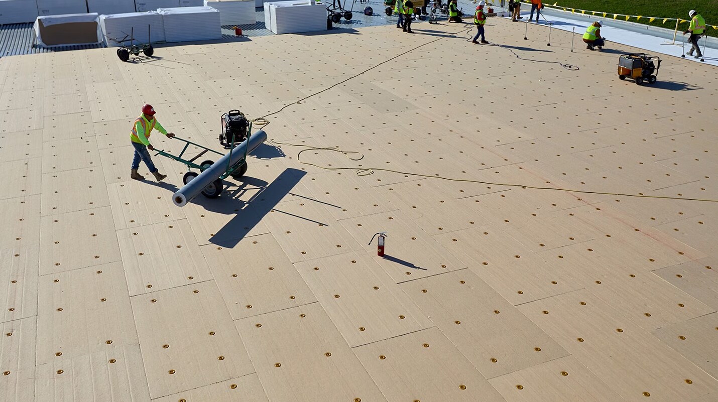
Roof systems often have a significant number of thermal bridges, whether the insulation is mechanically attached and the membrane is adhered, or if the membrane is mechanically attached with minimal fasteners holding down the insulation. Where the fasteners and plates are located vertically within the layers of a roof is critical to the overall thermal performance of the insulation layer. The photo below (Figure 1) is of an adhered roof system. The photo shows a distinct pattern of "dots" of melted snow which are caused by interior heat loss through the fasteners and plates at each fastener location.
Figure 1: A photo showing melted snow at each fastener and plate location of this adhered membrane roof system.
To explain–the fasteners and plates are securing the full thickness of insulation. This means the fastener head and plate are immediately below the adhered membrane, and the fastener shank is fastened into the roof deck. The fastener shank acts as a thermal bridge between the interior and exterior. Heat from the interior is transferred to the exterior because the metal shank is a good conductor of heat. The heat from the shank also increases the temperature of the plate, which acts as a radiator, dissipating heat very efficiently to the exterior. And as the plates lose heat to the exterior, more heat is transferred from the interior to the exterior. This transfer of heat happens essentially 24 hours a day. The greater the temperature differential between the interior and the exterior, the greater the heat transfer.
While the photo shows the effects of heat loss during cooler months. The effect is reversed in the warm months–the heat from the exterior is transferred into the building, which can cause the HVAC system to work harder to keep the interior temperature consistent. An HVAC system that is required to make up for loss of heat (during winter months) and heat gain (during warm summer months) will likely require more energy and cost to operate.
All that being said, what is the actual loss of R-value of a roof's thermal insulation layer when fasteners and plates are installed through the entire thickness of insulation? To help answer that question, two important pieces of modeling and research have been conducted in recent years.
Fastener Location – Modeling Results
Modeling (Taylor, et al, "Insulation Value Optimization for Low-Slope Roofs") showed varying losses of R-value when fasteners and plates were installed at different locations within the insulation layer. The model, for the cases shown in Figure 2, started with a design R-value of 30 and used a 15,000 sq. ft building with the number of fasteners that would be typical for a 120 mph wind region.
A traditional mechanically attached system (with an overall fastener density of 1 fastener per 2 square feet) was modeled and showed a 17% loss of R-value. An induction welded system was modeled with fasteners and plates just beneath the membrane; this system showed a 12% loss of R-value. Installing the fasteners and plates under a 3.8" layer of polyiso was modeled and showed only a 4% loss of R-value. Installing the fasteners and plates into a ½" rigid board just above the roof deck with all layers of polyiso about resulted in a 1.5% loss of R-value. The graphic below (Figure 2) summarizes the R-value loss from fasteners (i.e., thermal bridges) that were modeled in the study by Taylor, et. al.
Figure 2: Representative graphics showing modeled R-value loss due to fastener and plate location within a roof system.
Regardless of the exact values shown, the takeaway from this modeling study is that burying fasteners and plates further down into the overall thickness of the insulation layer greatly reduces the loss of effective R-value of the insulation layer. In other words, adhering the layers of polyiso above a mechanically attached rigid board is an effective way to retain the design R-value.
Fastener Location – Research Results
Physical research (Grant, et al, "Assessment of Thermal Bridging of Fasteners through Insulated Roof Assemblies") showed slightly different results, but the R-value loss from fasteners and plates was still found to be significant. The physical research was performed on a 2 foot by 2 foot sample in a large controllable climate test chamber. The research looked at 3 scenarios: 1) polyiso only, 2) polyiso with cover board, 3) polyiso with cover board and steel deck. Each was tested to determine R-value without a fastener and with a single fastener and plate. Importantly, the fastener density was 1 fastener per 4 square feet. This research found a loss of R-value of nearly 5% when the fastener and plate were installed above the polyiso, directly under the membrane, and no cover board was used. This generally aligns with the modeling done by Taylor that showed a 12% loss of R-value when fastener density is considered. Taylor showed 2½ times the loss of R-value with a 2 times greater fastener density.
The ultimate point of the modeling and research is that fasteners and plates that secure the full thickness of thermal insulation in combination with steel decks can significantly reduce the effective R-value of a roof's thermal insulation layer.
Single vs Multiple Layers of Insulation
The design of the thermal insulation layer plays a large part in the effective R-value of a roof system. There was a time when single-layer insulation was commonplace, and the butt joints were continuous from the top of the roof deck to the underside of the membrane. Proper installation calls for tightly abutting adjacent insulation boards. However, air flow happens, and no matter how tightly the boards were butted, there is some amount of airflow from the deck to the membrane through the butt joints. The airflow at the butt joints exchanges heat between the interior and the exterior, resulting in a loss of R-value for the overall thermal insulation layer. Information reported by NRCA in The NRCA Roofing Manual: Membrane Roof Systems–2023, Appendix 6, shows an approximate 4-6% loss of R-value for 5 inches of single-layer insulation. NRCA also reports that using two layers of insulation installed in an offset and staggered pattern reduces the airflow from deck to membrane by about 2/3rds. This research and information is part of the basis that has been used to improve energy codes. The International Energy Conservation Code–as of 2018–requires roof insulation to be installed in at least two layers, with the board joint offset and staggered.
Multiple layers of insulation benefits the overall effectiveness of a roof's thermal insulation layer considerably, as shown by the research presented in the NRCA manual.
Air barriers at the Deck
While multiple layers of polyiso installed in an offset and staggered pattern helps reduce airflow within a roof system, the use of an air barrier at the roof deck beneath the insulation layer can prevent nearly all air from moving from the interior into the roof system. Air moving from the interior to the underside of the roof membrane moves heat and moisture in and out of the roof system. The movement of heat via air movement reduces the effective R-value of the roof's overall insulation layer. In addition to transferring heat, air movement can move large quantities of moisture as well. Air barriers can provide many benefits to the effectiveness of insulation and the longevity of a roof system.
The International Energy Conservation Code–as of 2015–requires air barriers be provided throughout the building thermal envelope, and they are allowed to be on the inside, outside, or within the building envelope. This language allows the roof membrane to be the air barrier. However, as discussed, if the roof membrane is considered to be the air barrier, air can move from the interior of the building into the roof system. Ideally, an air barrier in a roof system should be installed beneath the insulation layer just above the deck. Additionally, air barriers, in order to work effectively, must be sealed at penetrations and at perimeters. Proper detailing of penetrations and perimeters should be done during design and installation.
Conclusion
While low-temperature R-value is a concern, and one that is continually being dealt with by manufacturers, the proper design of a roof's thermal insulation layer should take into account many additional considerations.
Fasteners used to secure insulation for an adhered roof membrane should be beneath at least one layer of rigid insulation, or beneath an adhered cover board
Use at least two layers of rigid insulation, and stagger and offset the board joints
Use an air barrier at or just above the roof deck
Use polyiso insulation that has low-temperature-stable R-value
Designing and installing a roof's thermal insulation layer as an effective insulating layer that retains the highest effective R-value is something the roofing industry understands and should be working towards everyday.
Additional information is available from the following publications:
"Energy Resistance of Commercial Roofs," ASTM D08 Ninth Symposium on Roofing Research and Standards Development, December 2019
"Towards Codification of Energy Losses from Fasteners on Commercial Roofing Assemblies," IIBEC Interface, February 2020
"Mind the Gap," Professional Roofing, September 2020
